3D printed "spider" Delta Robot

Following the aims of my previous robot arm I developed a second one.
This one belongs to the family of "spider" Delta robots. In industrial applications it is mainly used for assembly purposes (Pick and Place)
Delta bots have the advantage that they have common parts for all the driving items (normally 3 or 4) thats simplify the construction.
I try to follow the philosophy of my previous thing that must be: small, cheap and easy to assemble but this time I had to use bigger servo (mg995) for the three main arms so this makes it a little bigger ( 400 x 450 x 450h mm of occupied volume comprehensive of structure).
3D models in stl format can be downloaded for free at Thinghiverse.
Detailed instruction at Instructables.
Demo video on YouTube.

Delta bots are characterized in that they are composed of multiple identical elements (usually three or four) that drive the plate, so in this case I explain how to assembly
one of it, than the sequence has to be repeated for the two remaining.
3D PRINTED PARTS LIST :
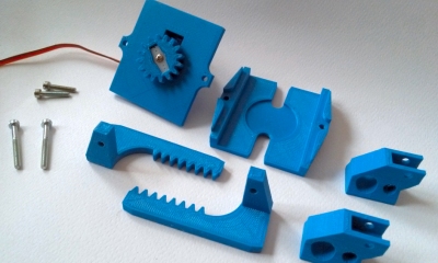
here following the LIST OF 3D PRINTED PARTS (with quantities)
n.1 EBD.01.01.002 mast.STL
n.3 EBD.01.01.003 corner.STL
n.3 EBD.01.02.001 support.STL
n.3 EBD.01.02.003 rx_arm.STL
n.3 EBD.01.02.004 sx_arm.STL
n.6 EBD.01.02.005 bridge.STL
n.3 EBD.01.02.006 feet.STL
n.1 EBD.01.02.007 plate.STL
n.1 EBD.03.00.001 base plate.STL
n.1 EBD.03.00.002 upper plate.STL
n.2 EBD.03.00.003 spur.STL
n.1 EBD.03.00.004 gear.STL
n.2 EBD.03.00.005 finger.STL
n.1 EBD.04.00.001 duct.STL
COMMERCIAL ITEMS B.O.M. (I use metric hardware)
n.3 MG995 servo
n.1 sg90s servo
n.3 604zz ball bearing
n.12 Uniball Traxxas M4x17 Crawler/Scaler
n.3 dia 16 x 1 l=220 mm aluminum pipes
n.3 dia 16 x 1 l=330 mm aluminum pipes
n.6 M4 x 200 mm long threaded rods
n.15 M3 nuts
n.12 M3 x 25 TCEI screw (receessed hex head)
n.2 M3 x 45 TCEI screw (receessed hex head)
n.6 3x15 self tapping screw
n.1 400 x 450 mm plywood sheet (for the base)

For hanging the robot and keep it in position, I designed a central elements and three legs.
Legs are composed each one by two printed parts and two aluminum pipes. They are not essential elements for the robot operation and may be used other methods of your choice if you prefer.
Anyway, If you want to use mine:.Drop in their housing the M3 nuts and connect the three main drive arms each other using M3x.. screw
Leave screws a little loosen to allow the "EBD.01.01.002 mast" to be inserted in the middle. Once inserted tight the M3 screws.

Insert one pipe Ø 16mm x 220mm long in the "EBD.01.01.004 corner". With a drill bit make an hole in aluminum pipe following the existing on the printed elbow then fix with a self tapping screw. Insert now the vertical pipe in the remaining housing and fix it in the same way as previous and put at the bottom the "EBD.01.02.006 feet" Repeat operations for the other two remaining legs.

Each connecting arms is composed by an M4 threaded rod 200mm long and two traxxas eye rod fixed by two M4 nuts. Is important to make a jig to be sure that all the arm have the same length. I made one using a wood tablet with two M3 screws locked in position. It is not so important the final length but assuring that all the rod have the same length. Once assembled all the six connecting arms, you have to attach them in a pair of two at the outer side of the driving arms..

ELECTRONICS & HOW TO MAKE IT ALIVE
The servo wires can find their route to exit the centre of robot through one diagonal rod as shown in picture (19)
OK it's done. Now you can leave it as it is, and use it as a cumbersome tabletop, or make it alive.
If the secon option is your choice, it is still a long way. I can suggest, to make it shorter, to follow my Instructables that I made to drive it (or any other robot made by 4
servos) using an Arduino, a Bluetooth module and an Android APP made with MIT Appinventor Android-APP-to-Control-a-3DPrinted-Robot.

ELECTRONICS & HOW TO MAKE IT ALIVE
As an alternative, I suggest the Pololu mini maestro. It is not so cheap (and also I do not earn money from them), but I must acknowledge that solve a lot of problem to
who is not so confident as me with electronics.( https://www.pololu.com/product/1353 )
You connect it to the PC via USB and using a free (great) software downlodable from their website you can drive the servo using slides on the ready interface (21).
You can also make them works in a fixed range of travel following acceleration and speed that you decide in the dedicated "Channel Setting" tab. But the most interesting
feature from my point of view, is that you can program a sequence simply storing one position after the other and then make it run in loop from "Sequence" tab.
(20) Connection are very simply: The USB cable from the PC has to be connected to the mini USB connection. Servo wiring has to be connected to the row of header pin
(in this case I use an alternate step). And then you have to provide adequate supply on the last row of header pins.
Like already explained in my previous robot arm, there are also several other ways to control it but I do not want to provide other ready made solution.
The purpouse was just that, produce a sufficiently reliable and ready hardware to allow users to explore they own way to control it.
da/theGHIZmo.
last update 24/01/17
VIEWS on Thingiverse
DOWNLOADS on Thingiverse
TOT VIEWS on YOUTUBE
VIEWS on Instructables
more makes from other Thingiverse users